In the following tutorial I will show how to make data logging for digital balance KERN 572 using Excel VBA (I will be exposed to LabView later). You probably may need this feature in cases where you are interested to measure instantaneous or average inlet/outlet/net mass flow rate for a tank or container placed on the balance. Also, you may use this feature to measure evaporation rate of certain fluid at ambient temperature. Measuring forces like lift force -for example- of an airfoil at different angles of attack.
The first application in my work where this feature was useful was a refrigerant charging station.
The second application for which I needed this feature was measuring mass flow rate of water bleeding from a Cylindrical acrylic tank used in WBT measurement device.
The following instructions are already stated in the manual of the balance with some modifications and illustrations I have added.
5. Interface RS 232 C
5.1 Technical Data
ƒ8-bit ASCII Code
ƒ1 start bit, 8 data bits, 1 stop bits, no parity bit
ƒBaud rate adjustable to 2400, 4800, 9600 (default), and 19200
ƒMiniature DIN plug is necessary type MP-371/C 7
ƒWhen working with an interface correct operation is secured only if the corresponding KERN-interface-cable (max. 2 m) is used.
5.2 Description of the jack
3 pins are only used for communication with KERN 572 digital balance

Pin 2: transmit data
Pin 3: receive data
Pin 5: signal ground
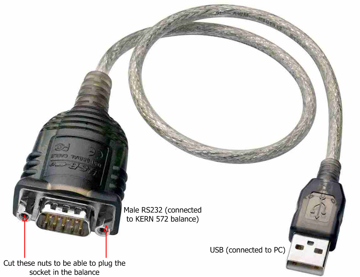
A prolific USB to RS 232 converter may be used for modern computers and laptops. The picture below shows SIEMENS converter cable I already used successfully.
If you don't have the driver of this converter cable you can download here
5.4 RS 232 C Data output via interface RS 232 C
5.4.1 General information
As a condition for the data transfer between the balance and a peripheral device (for instance printer, PC ...) both devise have to be set on the same interface parameter (for instance baud rate, parity ...).
There are 4 methods for the data output via RS 232 C:
1. Data output via PRINT-key (see 5.4.2).
2. Data output, after having loaded the balance, by setting AUTOPRINT (see 5.4.3).
3. Continuous data output by setting AUTOPRINT PC (see 5.4.4).
4. Data output by transfer of remote controls (see 5.4.5)
5.4.2 Data output via PRINT-Key
The printing process can be released by the PRINT-key. In this case the settings AUTOPRINT and AUTOPRINT PC should be deselected.
5.4.3 AUTOPRINT
The setting AUTOPRINT is in the PRINTER-routine, and there it can be selected or deselected. When AUTOPRINT is active the actual weighing value will be sent via the RS 232 interface when the balance has been unloaded and then loaded after having achieved
the stability.
5.4.4 AUTOPRINT PC
The setting AUTOPRINT PC is in the PRINTER-routine, and there it can be selected or deselected. When AUTOPRINT PC is active the actual weighing values will be sent continuously via the RS 232 interface.
5.4.5 Remote Control:
The following functions can be released by the remote controls that will be transferred as ASCII signs to the balance.
"t" Tare.
"w" a weighing value (or unstable) is sent via RS 232 interface.
"s" a stable weighing value is sent via RS 232 interface.
If the balance receives the command w or s, it acts without printing delay.
5.4.6 Description of the data transfer:
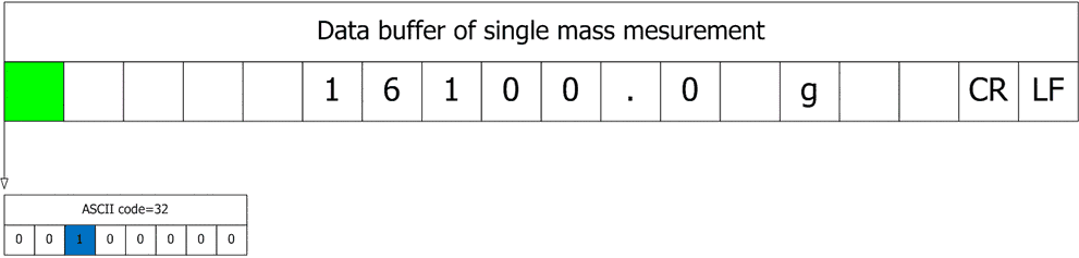
Structure of each data transfer:
Without Numerator:
Bit-Nr. 1 2 3 4 5 6 7 8 9 10 11 12 13 14 15 16 17 18
B* B B B B B B B B 0 . 0 B g B B CR LF
B*: = Blank or %in the range of zero point.
B, 0, ., g: = Blank or weighing value with unit, depending on the load on the
weighing plate.
CR: = Carriage Return
LF: = Line Feed
Each mass measurement is represented by a string buffer of 18 ASCII characters, each character is represented by 8-bits. See the animation below to see how the string buffer is composed.
Data buffers are separated by the line feed LF character (New line or Enter).
I made the last animation using this website
6. Options
6.1 Printer
With the serial data output RS 232 a printer can be connected. The printout shows the weight in grams. When the counting mode is selected the number of
pieces or the weight is printed.
When the percent mode is selected, the percentage or the weight will be printed. Press The PRINT-key to print weighing results. Select the enumerator to number the weighing continuously.
Turn off the balance or use the CLEAR function to Reset the enumerator to (000)
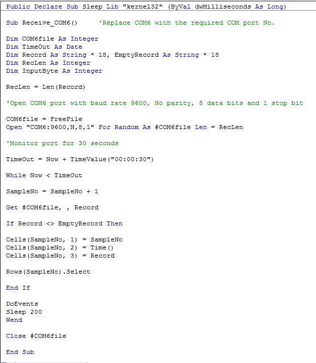
Setting sampling time in Excel VBA:
The sampling time may be adjustable or not. The following are the cases:
(A) If the PRINT key is used manually then the sample time will not be set, because if it is not pressed then nothing will be sent to PC (time out).
(B) If the AUTOPRINT mode is used then the sampling time should be more than or equal 2 seconds which is the typical stabilization time.
(C) If AUTOPRINT PC mode is activated then the sampling time will depend on Baud rate. The following formula is used to calculate the minimum sampling time based on Baud rate:
Minimum sampling time [Sec.]= Baud rate [bps]/(No. of data bytes in each measurement/string buffer * 10)
In AUTOPRINT PC MODE, in case of setting sampling time larger than minimum sampling time, each received data packet/batch will contain multiple measurements at a time.
(D) Sending "w" character to the balance (simulating the PRINT key action) then receiving measurement at the same time.
Configuring the balance:
Set Baud rate
Set the printing mode
Set enumerator
Communication procedure:
You have to set in Excel the following parameters before establishing the communication:
COM port number - No. of start bits - No. of data bits - No. of stop bits - Parity bit - Baud rate - String buffer length
Then you will open COM port (open channel)
Retrieve data - write to file
Close COM port at the end of measurement (close channel)
Communication using A&D WinCT Data Communication software:
You can download the software from here
WinCT software package has three programs: RSCom, RSWeight, and RSKey. After installation you can copy the program folder and use RSKey as a portable software on any PC.
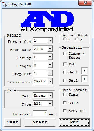
RSKey can read only the balance without writing to it. All what you have to do is to open an Excel sheet, then open RSKey, configure serial communication parameters, and finally click "Start" button. The software will paste data directly in the Excel sheet.
Caution: Don't click "Start" button when windows explorer in the background!!!
Press "Start" button only when "MS Excel", "Notepad", "MS Word", or any text processing software is in the background.
Fast case study:
I have tested the drainage time of water from the acrylic tank used in WBT device with the filling cap once, and without the cap another time.
With cap (small ventilation area):
Drained water: 1300 gm = 1300 mL
Drainage time: 265 seconds = 4 minutes: 25 seconds
Without cap (large ventilation area):
Drained water: 1298.1 gm = 1298.1 mL
Drainage time: 157 seconds = 2 minutes: 37 seconds
The first application in my work where this feature was useful was a refrigerant charging station.
The second application for which I needed this feature was measuring mass flow rate of water bleeding from a Cylindrical acrylic tank used in WBT measurement device.
The following instructions are already stated in the manual of the balance with some modifications and illustrations I have added.
5. Interface RS 232 C
5.1 Technical Data
ƒ8-bit ASCII Code
ƒ1 start bit, 8 data bits, 1 stop bits, no parity bit
ƒBaud rate adjustable to 2400, 4800, 9600 (default), and 19200
ƒMiniature DIN plug is necessary type MP-371/C 7
ƒWhen working with an interface correct operation is secured only if the corresponding KERN-interface-cable (max. 2 m) is used.
5.2 Description of the jack
3 pins are only used for communication with KERN 572 digital balance
Pin 2: transmit data
Pin 3: receive data
Pin 5: signal ground
A prolific USB to RS 232 converter may be used for modern computers and laptops. The picture below shows SIEMENS converter cable I already used successfully.
If you don't have the driver of this converter cable you can download here
5.4 RS 232 C Data output via interface RS 232 C
5.4.1 General information
As a condition for the data transfer between the balance and a peripheral device (for instance printer, PC ...) both devise have to be set on the same interface parameter (for instance baud rate, parity ...).
There are 4 methods for the data output via RS 232 C:
1. Data output via PRINT-key (see 5.4.2).
2. Data output, after having loaded the balance, by setting AUTOPRINT (see 5.4.3).
3. Continuous data output by setting AUTOPRINT PC (see 5.4.4).
4. Data output by transfer of remote controls (see 5.4.5)
5.4.2 Data output via PRINT-Key
The printing process can be released by the PRINT-key. In this case the settings AUTOPRINT and AUTOPRINT PC should be deselected.
5.4.3 AUTOPRINT
The setting AUTOPRINT is in the PRINTER-routine, and there it can be selected or deselected. When AUTOPRINT is active the actual weighing value will be sent via the RS 232 interface when the balance has been unloaded and then loaded after having achieved
the stability.
5.4.4 AUTOPRINT PC
The setting AUTOPRINT PC is in the PRINTER-routine, and there it can be selected or deselected. When AUTOPRINT PC is active the actual weighing values will be sent continuously via the RS 232 interface.
5.4.5 Remote Control:
The following functions can be released by the remote controls that will be transferred as ASCII signs to the balance.
"t" Tare.
"w" a weighing value (or unstable) is sent via RS 232 interface.
"s" a stable weighing value is sent via RS 232 interface.
If the balance receives the command w or s, it acts without printing delay.
5.4.6 Description of the data transfer:
Structure of each data transfer:
Without Numerator:
Bit-Nr. 1 2 3 4 5 6 7 8 9 10 11 12 13 14 15 16 17 18
B* B B B B B B B B 0 . 0 B g B B CR LF
B*: = Blank or %in the range of zero point.
B, 0, ., g: = Blank or weighing value with unit, depending on the load on the
weighing plate.
CR: = Carriage Return
LF: = Line Feed
Each mass measurement is represented by a string buffer of 18 ASCII characters, each character is represented by 8-bits. See the animation below to see how the string buffer is composed.
Data buffers are separated by the line feed LF character (New line or Enter).
I made the last animation using this website
6. Options
6.1 Printer
With the serial data output RS 232 a printer can be connected. The printout shows the weight in grams. When the counting mode is selected the number of
pieces or the weight is printed.
When the percent mode is selected, the percentage or the weight will be printed. Press The PRINT-key to print weighing results. Select the enumerator to number the weighing continuously.
Turn off the balance or use the CLEAR function to Reset the enumerator to (000)
Setting sampling time in Excel VBA:
The sampling time may be adjustable or not. The following are the cases:
(A) If the PRINT key is used manually then the sample time will not be set, because if it is not pressed then nothing will be sent to PC (time out).
(B) If the AUTOPRINT mode is used then the sampling time should be more than or equal 2 seconds which is the typical stabilization time.
(C) If AUTOPRINT PC mode is activated then the sampling time will depend on Baud rate. The following formula is used to calculate the minimum sampling time based on Baud rate:
Minimum sampling time [Sec.]= Baud rate [bps]/(No. of data bytes in each measurement/string buffer * 10)
In AUTOPRINT PC MODE, in case of setting sampling time larger than minimum sampling time, each received data packet/batch will contain multiple measurements at a time.
(D) Sending "w" character to the balance (simulating the PRINT key action) then receiving measurement at the same time.
Configuring the balance:
Set Baud rate
Set the printing mode
Set enumerator
Communication procedure:
You have to set in Excel the following parameters before establishing the communication:
COM port number - No. of start bits - No. of data bits - No. of stop bits - Parity bit - Baud rate - String buffer length
Then you will open COM port (open channel)
Retrieve data - write to file
Close COM port at the end of measurement (close channel)
Communication using A&D WinCT Data Communication software:
A&D WinCT delivers technological achievements with the utmost simplicity. A&D's new WinCT software includes two programs (RSCom and RSKey) and is specifically designed for use with A&D Balances equipped with an RS232C interface and your PC. The software is compatible with Windows, Window 95, 98 & NT.
Addition:
1. The software can be used successfully with KERN digital balance.
2. The software is compatible with windows XP and windows 7.
You can download the software from here
WinCT software package has three programs: RSCom, RSWeight, and RSKey. After installation you can copy the program folder and use RSKey as a portable software on any PC.
RSKey can read only the balance without writing to it. All what you have to do is to open an Excel sheet, then open RSKey, configure serial communication parameters, and finally click "Start" button. The software will paste data directly in the Excel sheet.
Caution: Don't click "Start" button when windows explorer in the background!!!
Press "Start" button only when "MS Excel", "Notepad", "MS Word", or any text processing software is in the background.
Fast case study:
I have tested the drainage time of water from the acrylic tank used in WBT device with the filling cap once, and without the cap another time.
With cap (small ventilation area):
Drained water: 1300 gm = 1300 mL
Drainage time: 265 seconds = 4 minutes: 25 seconds
Without cap (large ventilation area):
Drained water: 1298.1 gm = 1298.1 mL
Drainage time: 157 seconds = 2 minutes: 37 seconds


