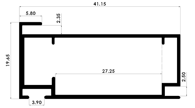
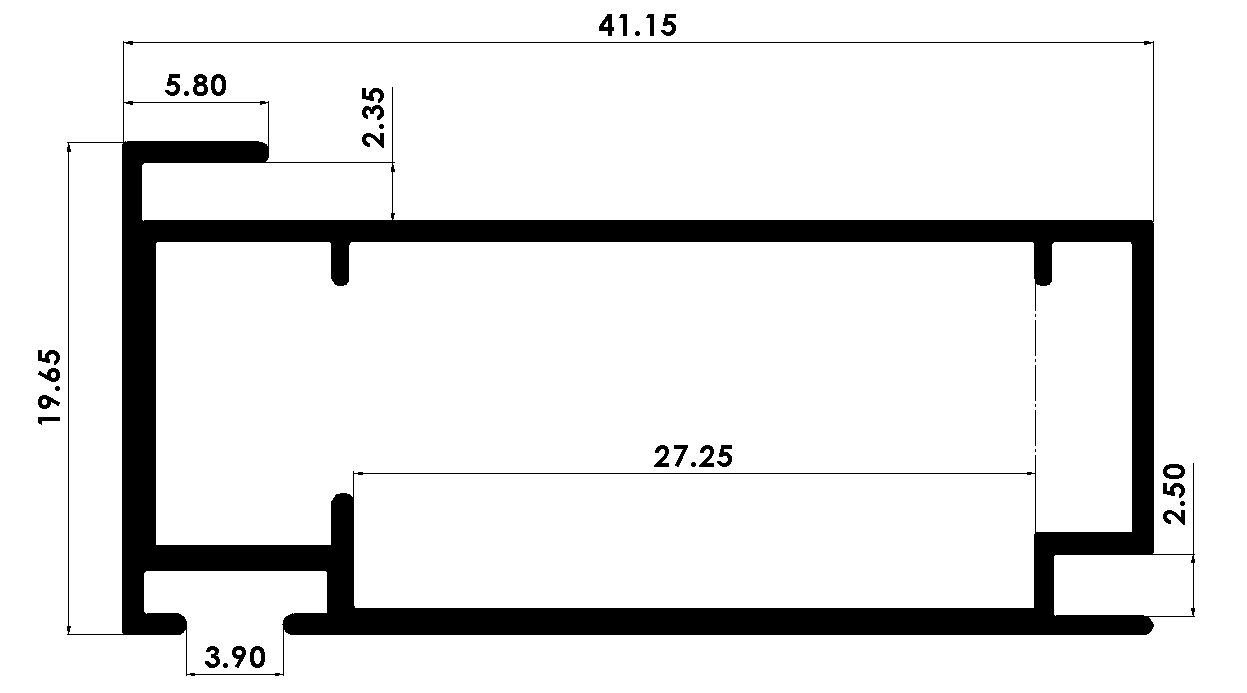
The following cross-section drawing shows one of the commonly used aluminum profiles in kitchen cabinets in Egypt. It is usually used for cabinet door frames. I drew this profile myself using a scrap piece (it was painted) from a nearby aluminum workshop. The real dimensions may slightly vary because of painting thickness. The drawing shows only the governing dimensions of the profile in millimeters. You can also download the CAD model of the profile from this link.
Orthogonal bars of this profile are connected at door frame corners using the following plastic connector or joint (in the render below). You can download the CAD model from this link.

Tags and keywords:
Kitchen cabinet door frame aluminum profile dimensions
Kitchen cabinet door frame aluminum profile drawing
Kitchen cabinet door frame aluminum profile Egypt
Kitchen cabinet door frame aluminum profile 3D cad model
Kitchen cabinet door frame aluminum profile
Kitchen cabinet door frame aluminum profile STL
Kitchen cabinet door frame aluminum profile assembly
Kitchen cabinet door frame aluminum profile plastic connector