Two weeks ago I bought a 2.8" 320x240 pixels RGB color TFT display having graphics driver chip ILI9341 and using Serial Peripheral Interface SPI for communication with Arduino board. You can find the display details in this link:
https://uge-one.com/arduino-2.8-inch-spi-tft-module.html?search=tft&description=true
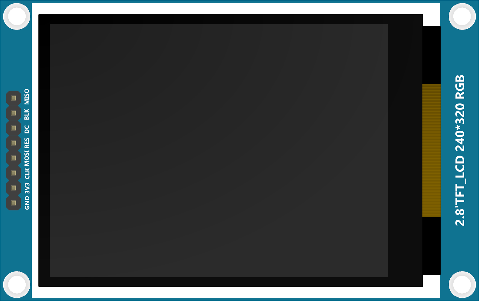
The display has 8 pins as shown in the picture below. Unfortunately, this screen does no have Chip Select CS (Slave Select SS) pin which is required if you are interfacing multiple SPI devices. Apart from the power pins (GND and VCC), this display needs only 4 digital pins to operate successfully and these pins are: CLK, MOSI, RES, and DC.
Pins BLK and MISO are optional and are not mandatory for operation of the display. In case you want to connect MISO pin with Arduino board, you can connect it directly because Arduino digital pins read any voltage level above 1.5V as digital HIGH.
This display is powered through VCC pin using 3.3V and for this reason all incoming signal levels should be within 3.3V. Powering this display with 5V will not harm or damage the screen immediately, but will turn the whole screen into white. These signal levels can be achieved using the simple voltage divider circuit as the shown in the images below.
The following is wiring of this display with Arduino Uno using hardware SPI interface (click the image to see it on full scale).

The following is wiring of this display with Arduino Uno using software SPI interface (click the image to see it on full scale). You can use different digital pins and define them in the code.

From software side of view, this display can be integrated with Arduino (I am using Arduino IDE 1.8.3) using one of two options:
First option:
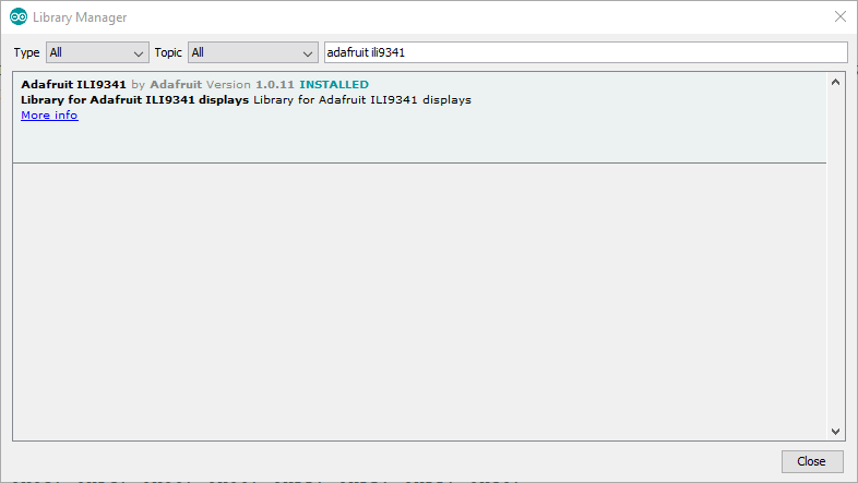
Using both: Adafruit GFX library and Adafruit ILI9341 library. You can download these libraries using the library manager in Arduino IDE as shown in the images below.

To kick off the coding, the code below is used to draw a black screen with a white rectangle drawn in the middle.
#include "SPI.h"
#include "Adafruit_GFX.h"
#include "Adafruit_ILI9341.h"
// For the
Adafruit shield, these are the default.
#define TFT_DC 9
#define TFT_CS 10
#define TFT_RES 8
// Use hardware
SPI (on Uno, #13, #12, #11) and the above for CS/DC
Adafruit_ILI9341
tft = Adafruit_ILI9341(TFT_CS, TFT_DC,TFT_RES);
// In case you
want to use software SPI, define pin numbers above and uncomment the line
below
//Adafruit_ILI9341
tft = Adafruit_ILI9341(TFT_CS, TFT_DC, TFT_MOSI, TFT_CLK, TFT_RES, TFT_MISO);
void setup() {
tft.begin();
tft.setRotation(1); // Use screen
horizontally
tft.fillRect(0,0,320,240,0x0000); //fill the screen
with black rectangle
tft.fillRect(80,60,160,120,0xFFFF); // draw white
rectangle in the middle
}
void loop(void) {
}
|
Second option:
Using UCGlib library. This library also is available from Arduino library manager. To learn more about this library you can go to reference page from this link

To make things easier, here is a very simple code for this library as well.
#include "SPI.h"
#include "Ucglib.h"
#define TFT_DC 9
#define TFT_CS 10
#define TFT_RES 8
// Hardware SPI
Ucglib_ILI9341_18x240x320_HWSPI
ucg(TFT_DC,TFT_CS,TFT_RES);
// In case you
want to use software SPI, define pin numbers above and uncomment the line
below
//Ucglib_ILI9341_18x240x320_SWSPI
ucg(TFT_CLK,TFT_MOSI,TFT_DC, TFT_CS,TFT_RES);
void setup() {
ucg.setRotate90();
ucg.setColor(0,0,0);
ucg.drawBox(0,0,320,240);
ucg.setColor(255,255,255);
ucg.drawBox(80,60,160,120);
}
void loop() {
}
|
Keywords:
Egypt UGE 2.8" (2.8 inch) SPI RGB TFT LCD screen display 320x240 wiring circuit diagram
Egypt UGE 2.8" (2.8 inch) SPI RGB TFT LCD screen display 320x240 code
2.8" (2.8 inch) SPI RGB TFT LCD screen display 320x240 driver IC chip ILI9341
SPI TFT display without Chip Select CS pin
SPI TFT display without Slave Select SS pin
8 pin SPI TFT LCD screen display 320x240
Cheap Chinese SPI TFT LCD screen display 320x240
SPI TFT display without Slave Select SS pin
8 pin SPI TFT LCD screen display 320x240
Cheap Chinese SPI TFT LCD screen display 320x240